Logic
Edited by Jen Moreau


COMPUTER SCIENCE
LOGIC
A large number of electronic circuits (in computers, control units, and so on are made up of logic gates. These process signals which represent true or false.

)
- Truth values, true and false, denoted T and F, respectively.
- Boolean values, 1 and 0.
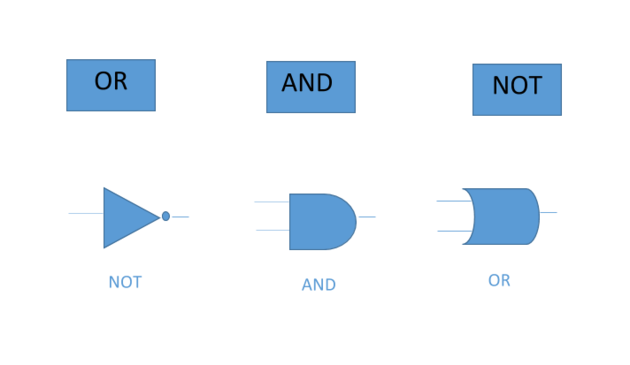
The 2- input AND will only give a logical 1 if both inputs are 1. The 2- input OR gate will only give a 1 output if either or both of the inputs are 1. The NOT gate will give a 1 output if the input is 0, and a 0 output if the output is 1 i.e it will invert the input. The results of putting inputs through the deferent gates can be summarized in a truth table below;


OR TRUTH TABLE

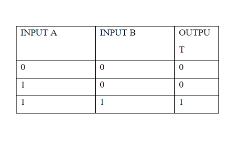
AND TRUTH TABLE

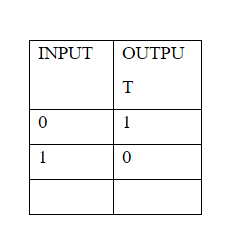
NOT TRUTH TABLE
NAND and NOR gates are also common, these gates are simply an AND or OR gate which has a NOT gate directly after it, thus the NAND and NOR gates output will simply be the inverse of the result of an AND or OR gate. Exclusive OR (XOR) and exclusive NOR (XNOR) gates are also widely found. The XOR gate gives 1 output when inputs are different, i.e one is 1 and the other is 0. The XNOR gate acts as a comparator, it gives a 1 output only if two input is the same.
The operation of the logic is analogous to the operations of a Boolean algebra. A Boolean algebra is a set on which certain axioms are stashed such as commutativity, associativity, a distribution law, existence of a zero element, unity, and complements. Thus Boolean algebra can be used to examine how logic gate work. The AND operation is written as A AND B = A: B, while OR is written A OR B = A+B, compliments are written with a bar A. some useful identities for manipulating equations are De Morgan's law A: B =A+B
Logic gates can be combined in different ways to construct more advanced circuits one common example being the J-K flip-flop. This is built from NAND gates and is capable of 'storing' a bit, a logical 1 or 1; essentially it can be set to a stable value depending on the inputs. The flip-flop has two parts, one for storing the bit (the slave) and one which is used to reset it based on the particular values of the input (master). If the inputs of the labeled J and K, are 1 and 0, respectively, then the inputs labeled Q and Q, are 1 and 0. The slave will only change state when the clock pulses and the inputs have changed, however, if but inputs are 1 continuously then the outputs will change every time the clock pulse.
NAND and AND Gate
An integrated circuit was selected which contained several NAND gates. This was powered, and the input were connected to logical switches, and the inputs were connected to a LED. The logic of a NAND gate was varied.
A NOT gate conjunction with the NAND gate was used to verify the logic and the AND gate.
NOR and OR Gates
An OR gate and a NOR gate were constructed using AND and NOT gate. The logic of the NOR and OR gates was varied.
EXCLUSIVE OR AND EXCLUSIVE NOR CIRCUITS Other ways of presenting logic gate and its circuitry are as follow;
SIMPLE GATE


AND GATE: The symbol and truth table for an AND gate is shown below:
If the inputs A and B are high then the input is high, often a (.) dot is used to signify the AND operator when writing Boolean equations.
OR Gate (sometimes referred to as an inclusive OR). The symbol and truth table for an OR gate is shown below:


If inputs A OR B are high (or both) then the output is high.
Often a (+) is used to signify the OR operator when writing Boolean equations.


The output is NOT what the input is. They are called inverters.
COMPLEX GATE
- NAND GATE:
Made by combining an AND gate and a NOT gate. The equivalent circuit is:
The symbol and truth table for a NAND gate is shown below;


- NOR GATE: Made by combining an OR gate and a NOR gate. The equivalent circuit is;
The symbol and truth table for NOR gate is shown below;


- XOR GATE: (Exclusive OR) Then gives a high output when A OR B are high, but not both. The equivalent circuit is;
The symbol for a XOR gate is


A+B = A.B+A.B
XOR gates are represented with a (+) symbol
BASIC BOOLEAN EQUATIONS
When designing circuits it is useful to be able to simply logic equations. By simplifying the equation of a circuit, we can reduce the number of gates that will be needed to implement the circuit when it is constructed. This has cost and performance benefits.
The following equations are used to reduce logic equations:
NOT
A=B
OR
A+0 = A
A+1 = 1
A+A = A
A+A = 1
AND
A.1 = A
A.0 = 0
A.A = A
A.A = 0
ASSOCIATIVE
A+(A+B) = ?(A+B)+C
A.(A.C) = (A.B).C
DISTRIBUTIVE
A.(B+C) = A.B-A.C
A+B.C = (A-B).(A+C)
COMMUTATIVE
A-B = B+A
A.B = B.A
Remember that the optimal solution is not always the solution with the fewest gates. In terms of cost, the optimal solution is generally that solution which has the fewest logic chips, assuming that the cost of logic chips does not differ greatly for different logic gates. (a chip which contains four AND gates cost roughly the same as a chip with for OR gates). This has not always been the case.
De Morgan's Rules
These can be a bit tricky to remember. And aid to memory is " if you break the line you change the sign".
A+B = A.B
A.B = A+B
KARNAUGH MAP REDUCTION
This method is a graphical aid to reducing logic equations its primary limitation is that is not effective for more than four variables. The map takes the form of a table laid out as shown below. The order of the possible variable states is important. A Grey code must not be used. A Grey code is a code in which at most one-bit changes in successive numbers
All the combinations which result in '1' as the result are marked in the table and grouped together. See the class example for the further information on grouping reduction.


Referencing this Article
If you need to reference this article in your work, you can copy-paste the following depending on your required format:
APA (American Psychological Association)
Logic. (2017). In ScienceAid. Retrieved Apr 25, 2024, from https://scienceaid.net/Logic
MLA (Modern Language Association) "Logic." ScienceAid, scienceaid.net/Logic Accessed 25 Apr 2024.
Chicago / Turabian ScienceAid.net. "Logic." Accessed Apr 25, 2024. https://scienceaid.net/Logic.
If you have problems with any of the steps in this article, please ask a question for more help, or post in the comments section below.
Comments
Article Info
Categories : Computer Science
