Transformer
Edited by Tosin Emmanuel, Sharingknowledge, Jen Moreau, SarMal


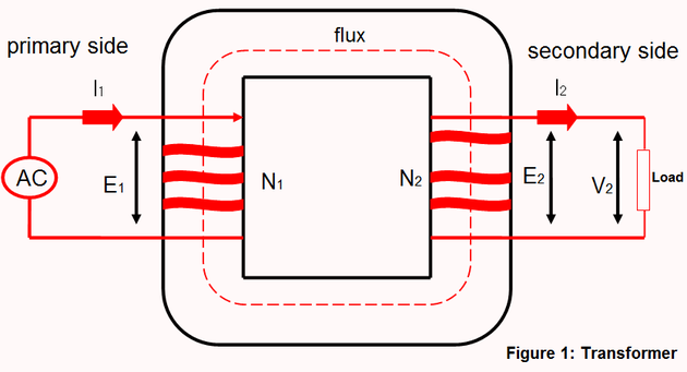
A transformer is an electromechanical device that changes the voltage level of an AC voltage. The main function of a transformer is the transference of electrical energy between circuits. This is done through electromagnetic induction. In 1831, Faraday discovered this transference of energy and since the invention of the first constant-potential transformer in 1885, transformers have become required components in electrical power distribution. A typical transformer is made up of the primary coil, secondary coil and a laminated soft iron core (Figure 1).

Transformer play an important role in electrical power generation; distributing generated voltage at the power plant to a very high voltage at the national grid and are also found at the transmission station to help transfer the voltage to a level that is useful to industries and distribution in urban and rural centers.
Transformer do not only work on AC voltage alone, but also perform several other functions; for example, transformers form isolation function, separating one stage electrically from the other in industrial equipment. These transformers are applied in instrumentation in substations to monitor the current/voltage being received from the transmission station.
Types of Transformers
There are two types of transformers:
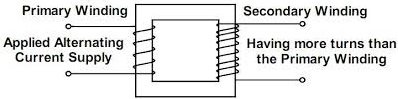
- 1As the name implies, a step up transformer steps up the incoming voltage to a higher voltage level. From the principle of electromagnetic induction, it is inferred that the number of turns in the primary coil is proportional to the magnitude of energy induced. In this case, the number of turns in the primary coil is less than the number of turns in the secondary coil, so the output coil is more than the input coil. If we denote the voltage at the primary coil to be Ep and the voltage at the secondary coil to be Es, the number turns to the primary coil to be Np and the number turns in the secondary coil to be Np, the current at the primary coil is Ip and the current at the secondary coil is Is. Mathematically, a step-up transformer:Step-up transformer.
Ep < Es, Np < Ns and Ip > Is.
Advertisement
The ratio N^s/N_p is called the turns ratio of the transformer and it is greater than one for a step-up transformer (Figure 2)

.
- 1As the name implies, a step down transformer steps down the incoming voltage to a lesser voltage level. In this case, the number of turns in the primary coil is more than the number of turns in the secondary coil, the output coil being less than the input coil. If we denote the voltage at the primary coil to be Ep and the voltage at the secondary coil to be Es, the number turns at primary coil to be Np and the number turns in the secondary coil to be Np, the current at the primary coil is Ip and the current at the secondary coil is Is. Mathematically a step-up transformer:Step down transformer.
Ep > Es, Np > Ns and Ip < Is.
The ratio N^s/N_p is called the turns ratio of the transformer and it is greater than one for a step-down transformer (Figure 3).


.
The Working Principle of a Transformer
When an alternating current (a current that changes periodically) voltage is connected to the input terminal (primary coil) of a transformer, an alternating magnetic flux is produced in the secondary coil and an alternating electromotive force is produced in the secondary coil. This process called mutual inductance and is defined as the flow of induced current in a coil due to an alternating current in a neighboring coil. The same magnetic flux link each turn of the primary and the secondary coil, also, the flux depends on the number of the coil in both the primary coil and the secondary coil. Mathematically,
Number of turns in the primary coil(N_p)∝E.M.F produced in the primary coil(E_p)
Number of turns in  secondary coil(N_s)∝E.M.F produced in the secondary coil(E_s)
N_p∝ E_p
Therefore,  k=N_p/E_p
N_s∝ E_s
Therefore,  k=N_s/E_s
Thus  E_s/E_p =  N_s/N_p
In an ideal transformer with 100% efficiency, the law of conservation of energy must exist in that transformer; the energy produced in the primary coil must be equal to the energy produced in the secondary coil. Hence, the power produced in the primary must be equal to the one produced at the secondary coil. In practice, there is always power loss due to the iron or magnetization loss, copper loss and heat loss thus, real life transformer does not have 100% efficiency. The efficiency of the transformer is defined as the ratio of the output power to the input power. Mathematically,
Efficiency=(Output power)/(Input power) = 100%
Efficiency=(Power in secondary coil)/(Power in primary coil) = 100%
Efficiency=(I_s E_s)/(I_p E_p ) = 100%
Referencing this Article
If you need to reference this article in your work, you can copy-paste the following depending on your required format:
APA (American Psychological Association)
Transformer. (2017). In ScienceAid. Retrieved Apr 27, 2024, from https://scienceaid.net/Transformer
MLA (Modern Language Association) "Transformer." ScienceAid, scienceaid.net/Transformer Accessed 27 Apr 2024.
Chicago / Turabian ScienceAid.net. "Transformer." Accessed Apr 27, 2024. https://scienceaid.net/Transformer.
If you have problems with any of the steps in this article, please ask a question for more help, or post in the comments section below.
Comments
Article Info
Categories : Electrical
Recent edits by: Jen Moreau, Sharingknowledge, Tosin Emmanuel
